After many seasons of raising his 35-pound CQR anchor with an old-fashioned manual windlass, the owner of this Downeast cruiser got tired of cranking. So he decided to equip her with a state-of-the art electric windlass, one that would not only drop and weigh his anchor effortlessly, but do so via a wireless remote control.
Windlasses are matched not to boat size or displacement but to the ground tackle. Used correctly the windlass doesn’t haul the boat to the anchor—motoring ahead while overhauling the rode is still the proper retrieval method—but takes over the heavy lifting when the anchor and chain are lifted off the bottom. Its maximum pulling power should equal or exceed four times the combined weight of the anchor, chain, and rope. This boat’s ground tackle weighs around 150 pounds.
Many excellent windlasses are available, but the owner wanted a Lewmar. Its Pro-Series 700 would have done the job, but to allow for future changes—adding chain, line, or a bigger anchor—he chose Lewmar’s Pro-Series 1000. He also replaced his old anchor rode with new high-test chain and Yale Brait by Yale Cordage. Brait is plaited from eight strands, woven rather than twisted together. It resists hockling (kinking and spreading), stays soft and pliable, and takes up less space in the anchor locker, so a longer rode fits in the same space. With a little practice, anyone conversant in marlinespike seamanship can splice it, too.
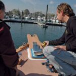
The owner asked Bill Jennings at New England Bow Thruster in Mystic, Connecticut, a Lewmar-authorized dealer and installer, to do the entire job. It took about eight hours. Here’s how Jennings did it.
This article originally appeared in the April 2008 issue of Power & Motoryacht magazine.
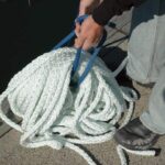
New Brait should be soaked before installation to tighten its lay.

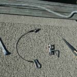
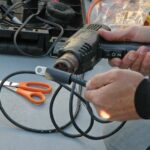
A Swedish fid for splicing Brait and Lewmar’s multitool flank the safety pennant that secures the anchor and the anchor swivel. The multitool is like a Swiss Army knife for the Lewmar windlass.
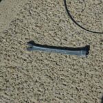
A close-up of the multitool, which you can use to manually raise the anchor
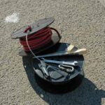
Jennings brought several reels of Anchor Marine wire for the installation.

Other items included foot switches for the up/down controls, various electrical connectors and of course, silicone sealant.
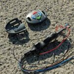
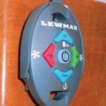
The wireless remote and receiving unit.
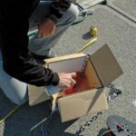
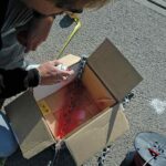
Jennings spray-painted several links of the chain red beginning about three feet back from the anchor. This will provide a visual warning that the anchor is almost weighed – handy when you’re using the remote control.
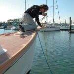
Two key measurements are the distance from the pulpit to the water and from the roller to the windlass.
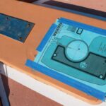
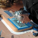
A Lewmar-supplied template shows Jennings where to drill the holes and where the silicone sealant should go. The circle in the middle marks the hawsehole.
The template must be taped to the deck before any drilling or cutting can take place.
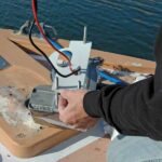
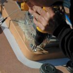
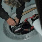
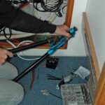
Once holes are drilled, the main wiring can be fed to below decks.
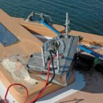
The windlass siliconed and ready to mount. Those fastenings are studs that are threaded into the windlass body.
The gasket is applied to the siliconed windlass.
Jennings made sure the gasket was clean, then slipped it over the studs, and applied silicone sealant where specified.
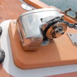
With the wires fed through the deck the windlass is carefully slid over the studs and into place.
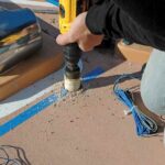
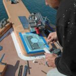
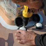
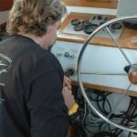
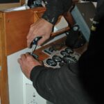
Jennings used a hole saw to cut the holes for the foot switches.
All wires were fed through the deck, and then the switches were dry-fit to check them for fit.
Both pads were positioned so that there would be enough toe room between them and the end of the pulpit.
Next, Jennings fastened both of the switches with wood screws.
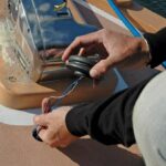
At the same time he also used several longer screws to fasten an eye strap for the wire safety pennant.
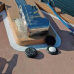
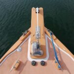
The exterior installation is basically completed, with the exception of a little touch-up painting.
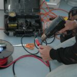
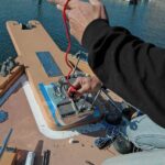
Jennings used #2 AWG wire for the windlass power circuit and #14 marine-grade cable for the foot switches. He protected all of the terminal ends with heat-shrink tubing.
To make sure he had the proper amperage, he drew current from the boat’s house-battery bank.
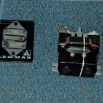
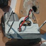
The windlass must be protected by a main circuit breaker mounted in an accessible spot.
Jennings chose the boat’s helm console right near the wheel, where it would be noticed if it tripped.
The breaker comes ready to install, with both spade and bolt connections.
The heavy-duty main wires connect to the bolt ends; they carry the heavy current to the windlass.

The circuit breaker simply attaches to the mounting surface with a couple of wood screws.
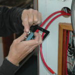
Jennings used a crimping tool to attached the terminal ends to the #14 wiring.
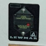
The circuit breaker in place. Jennings told the owner to shut it off when not using the windlass.
The wireless control can go most anywhere. Jennings selected a spot on top of the dash.
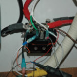
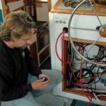
Finally, the receiver for the wireless control is soldered to the terminal block.
The windlass can be controlled from the foredeck by the foot pads or from anywhere on the boat by the wireless control. It can also control a bow thruster if the owner installs one.